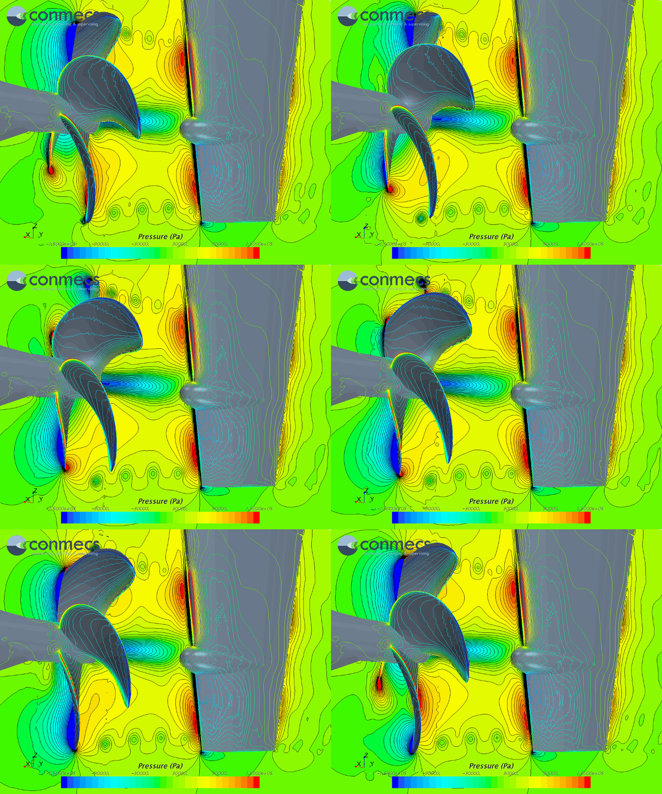
The design of rudders are usually based on class society rules. The required, minimum rudder area is estimated in relation to the ship’s wetted lateral hull area.
Rudder profiles come from old, successful shipbuilding projects. Rudder designs are often developed by another supplier, regardless of the propeller manufacturer. The positioning hull-propeller-rudder is traditionally based on experience from old projects.
To balance the rudder torque, the classification rules take the “static” position of the rudder areas in relation to the shaft into account. Dynamic effects from specific propeller inflow, during rudder laying and the influence of different rudder profiles on the shaft moment can not be captured by these formulas.
A check of the rudder axis with respect to balanced rudder moments in model tests is also very difficult due to the relative thicker boundary layer.
Therefore, conmecs recommends to investigate the whole system – hull, propulsor and rudder – in full-scale with RANSE methods during the design phase. Especially for new shipbuilding prototypes, where less experience is available.
If desired, in addition to the moments that occur, the following properties can be checked by CFD calculations:
- Rudder resistance taking into account the interaction with the hull and propeller
- Risk of damage due to cavitation
- Identification of energy losses that may be recovered by energy saving devices
- Extreme loads (e.g. during 35°-30° rudder steering test)

