
A ship propeller operates in a spatially non-uniform inflow field generated by the vessel hull, skeg and appendages. As the propeller rotates through this wake, each blade experiences continuously varying hydrodynamic loading.
This full-scale showcase combines transient propeller CFD with one-way Fluid–Structure Interaction (FSI) to investigate the relationship between the vessel wake, individual blade loading and the resulting structural response.
A Moving Reference Frame (MRF) solution is compared with a fully transient Sliding Mesh simulation to investigate the interaction between the propeller and the non-uniform vessel wake, from position-dependent blade loading in MRF to the transient structural response of blades rotating through the wake.
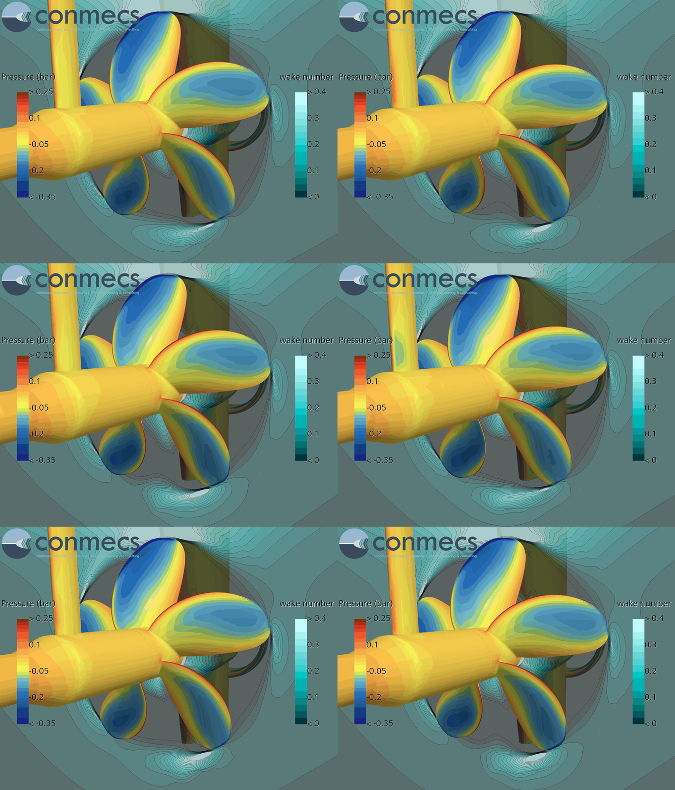
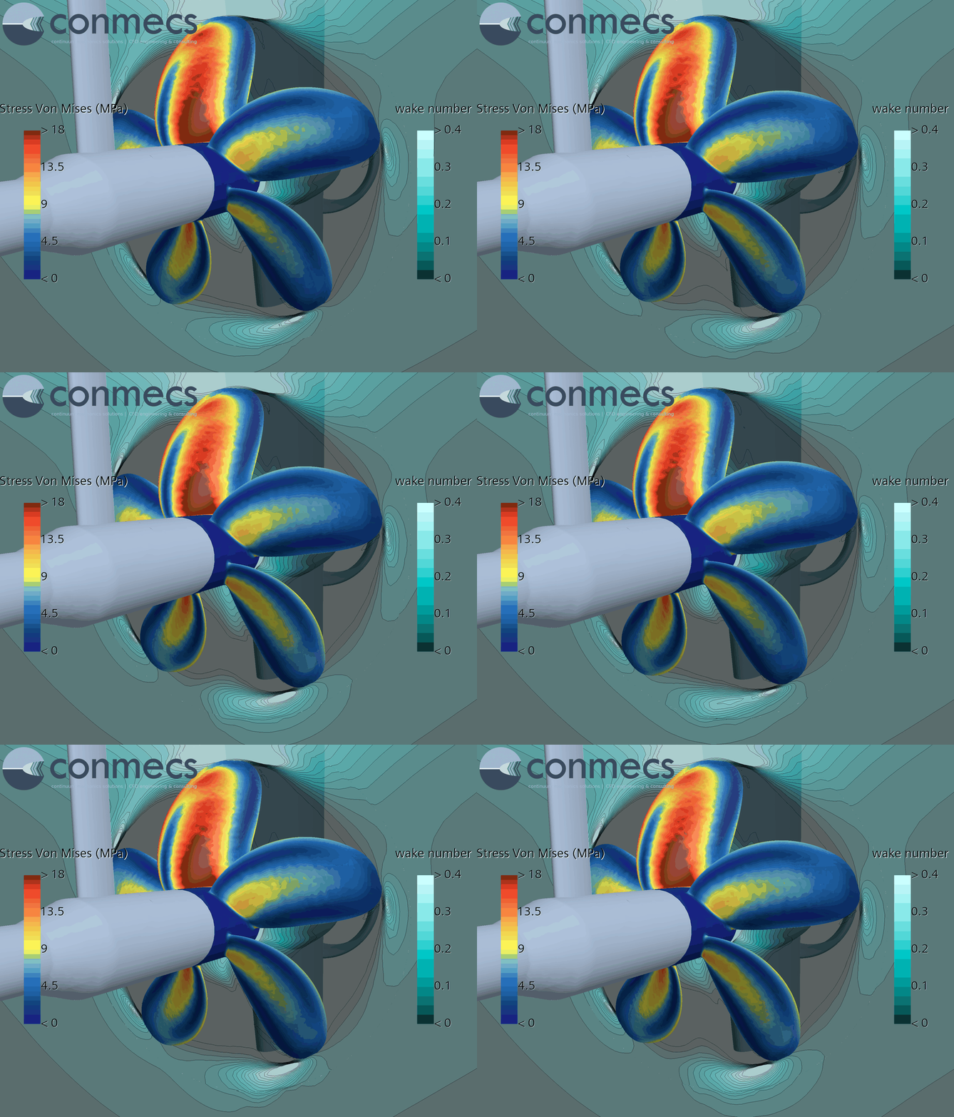
The Vessel Wake
The propeller operates in a spatially non-uniform inflow generated by the vessel hull, skeg and appendages. The axial wake distribution at the propeller plane provides a direct view of the inflow conditions encountered by the propeller.
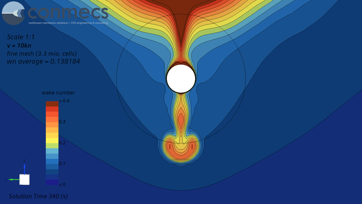
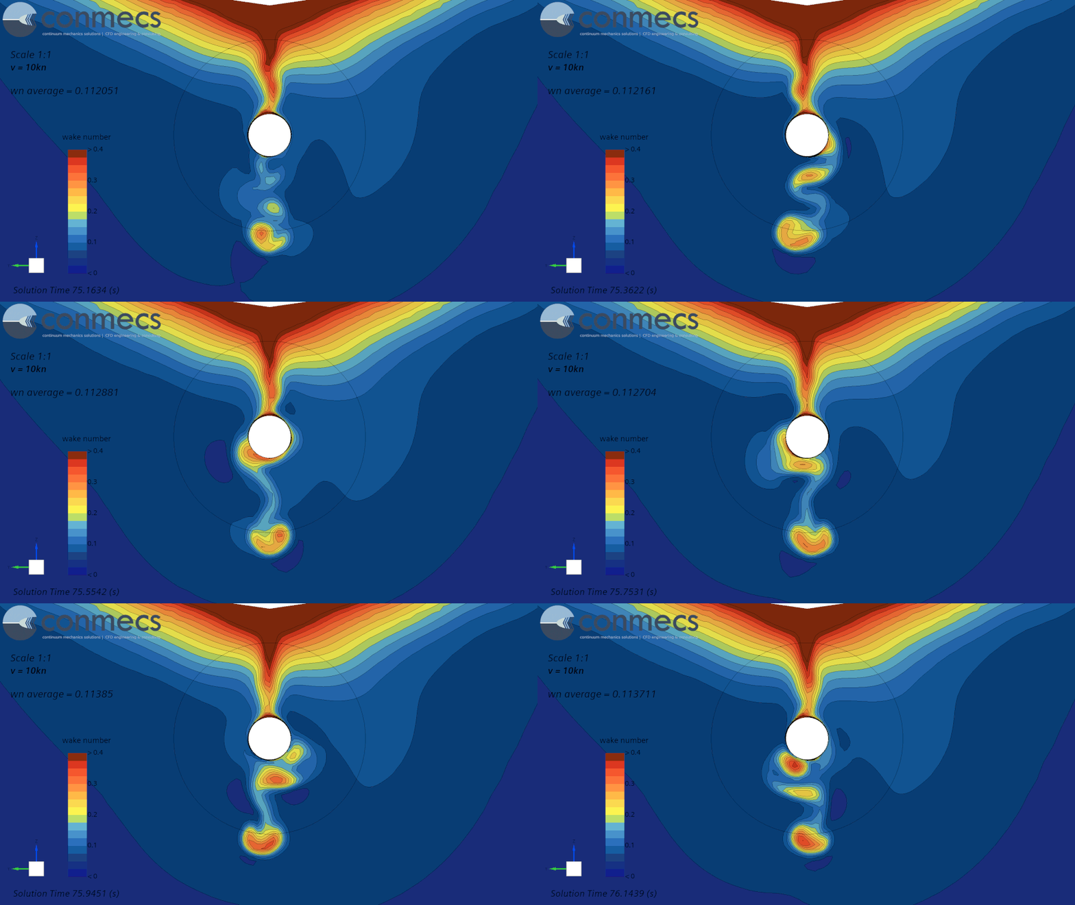
The first visualization shows the nominal wake field without the propeller, obtained from a resistance simulation including the vessel appendages. The axial velocity component is represented by the local wake number, revealing the characteristic spatial variation of the inflow across the propeller plane.
The second visualization shows the same section with the operating propeller included. The transient wake-number distribution now reveals the interaction between the rotating propeller, the incoming vessel wake and the upstream skeg.
The comparison illustrates that the propeller does not simply operate within a prescribed, stationary wake field. Its operation modifies the local flow field, while each blade simultaneously passes through the non-uniform inflow generated by the vessel.
These spatial and transient variations in the wake are the origin of the cyclic blade loading investigated in the following CFD and one-way FSI analysis.
From MRF to Sliding Mesh
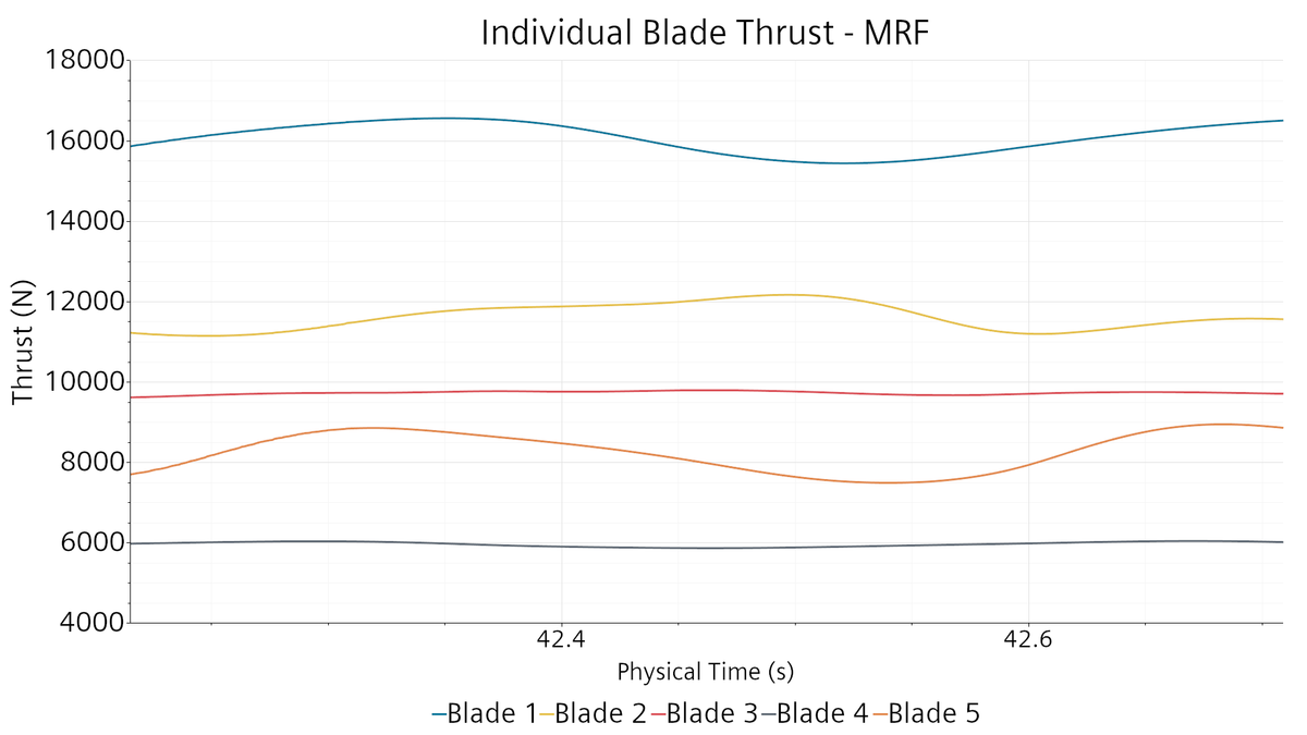
The influence of the non-uniform vessel wake can already be observed in the MRF solution. With the propeller at a fixed angular position relative to the wake, the five blades are exposed to different local inflow conditions and consequently develop different characteristic thrust and deformation levels. For example, Blade 1 is positioned near 12 o’clock, where the local wake conditions result in comparatively higher blade thrust and deformation.
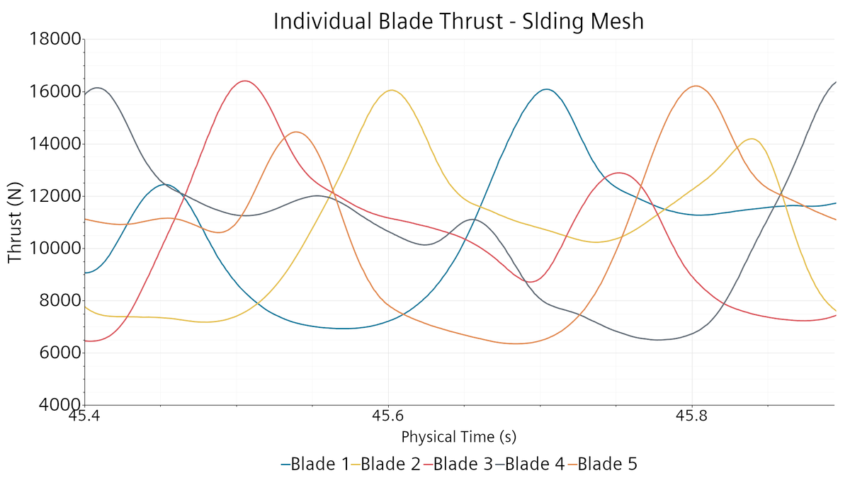
With Sliding Mesh, the actual rotation of the propeller through the wake field is resolved. Each blade successively passes through regions of higher and lower inflow velocity, producing a pronounced cyclic variation of hydrodynamic loading and structural response.
The following results compare the individual blade thrust and maximum blade displacement obtained with both approaches.
Individual Blade Thrust – MRF vs. Sliding Mesh
Maximum Blade Displacement – MRF vs. Sliding Mesh
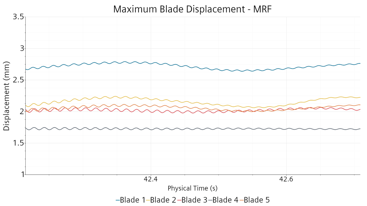
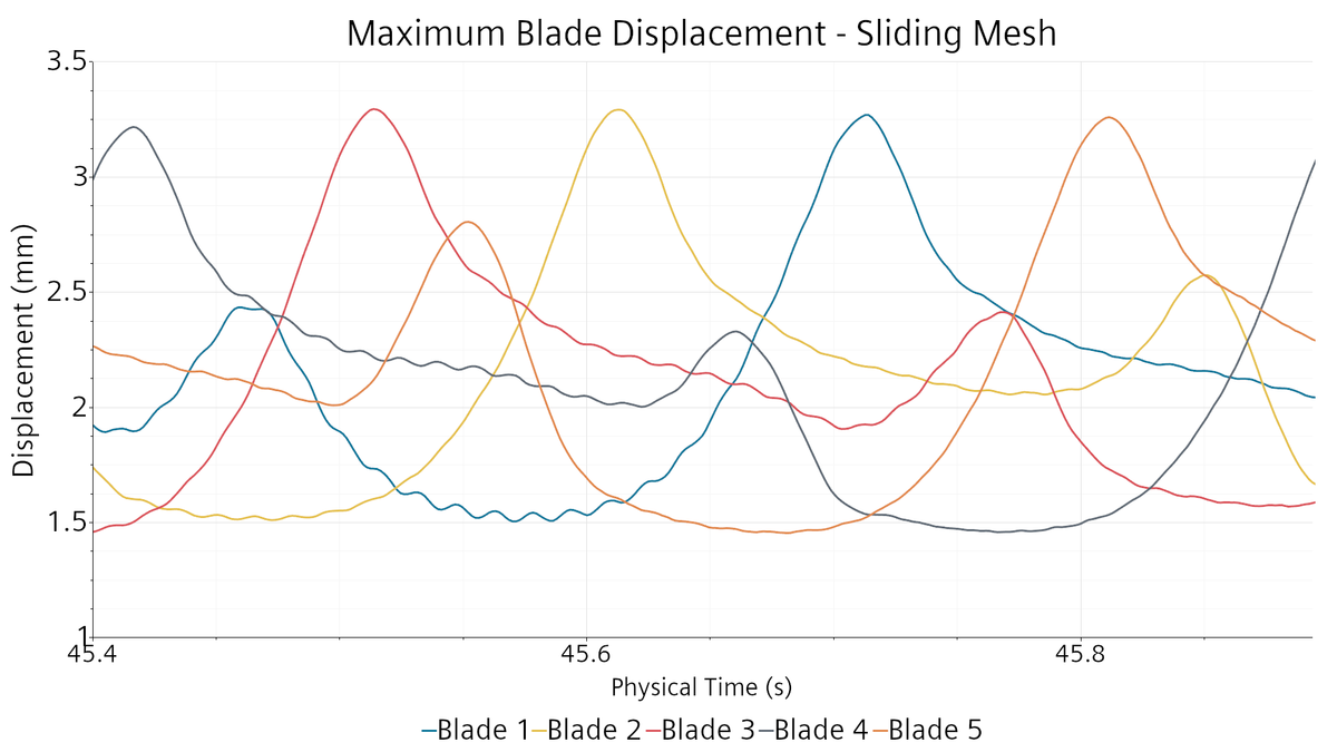
The contrast is clearly visible: in the MRF solution, the individual blades remain associated with their respective positions within the wake and show different characteristic load levels. In the Sliding Mesh simulation, all blades travel through the complete wake field and experience comparable cyclic load patterns, shifted according to their angular position.
The individual blade histories are similar, but not perfectly identical. The transient vessel wake itself contains unsteady flow structures, which are captured by the time-resolved CFD simulation.
One-Way Fluid–Structure Interaction
The transient CFD solution is coupled directly to a finite-volume structural model of the complete propeller using one-way Fluid–Structure Interaction (FSI).
Hydrodynamic pressure and shear loads acting on the blade surfaces are transferred to the structural model, allowing the instantaneous elastic response of each blade to be evaluated together with its hydrodynamic loading.
This provides a direct connection between the local vessel wake, the resulting blade forces and the structural deformation of the propeller.
Transient Response of the Complete Propeller
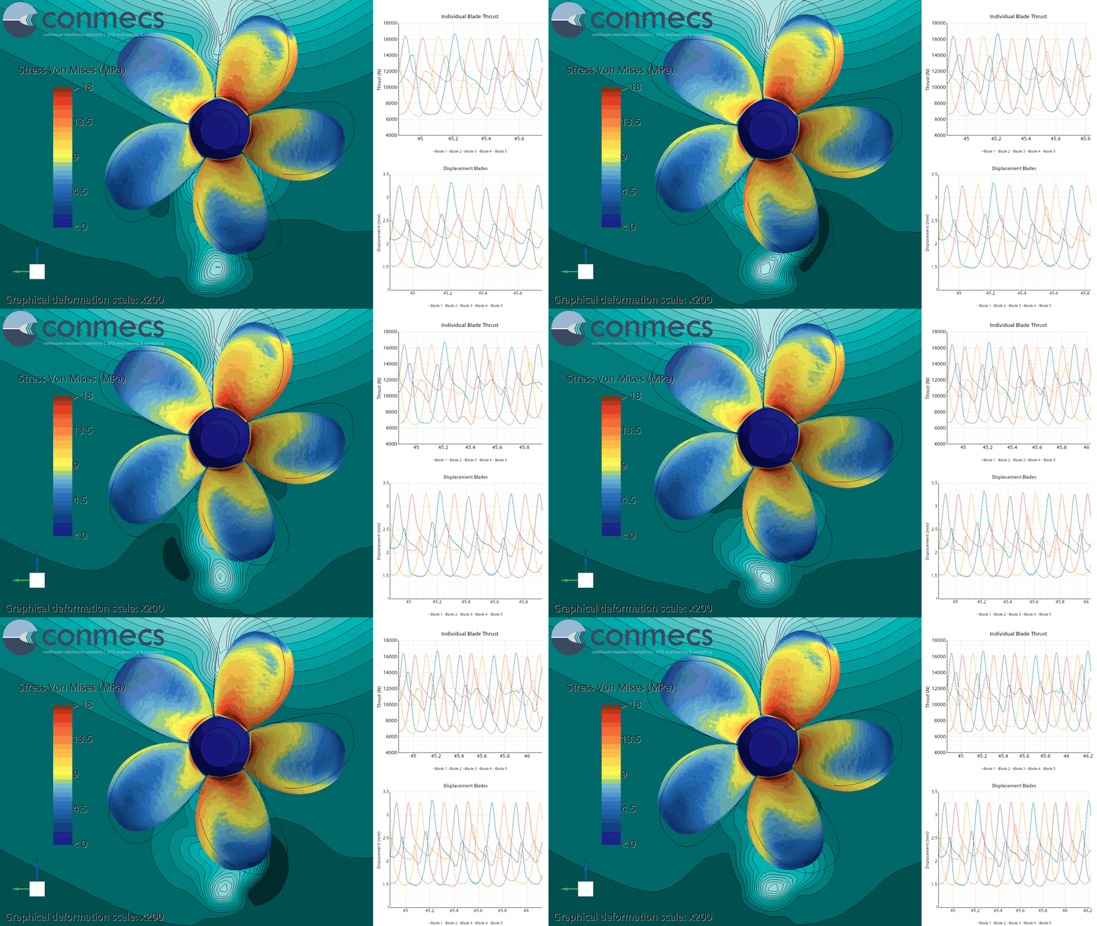
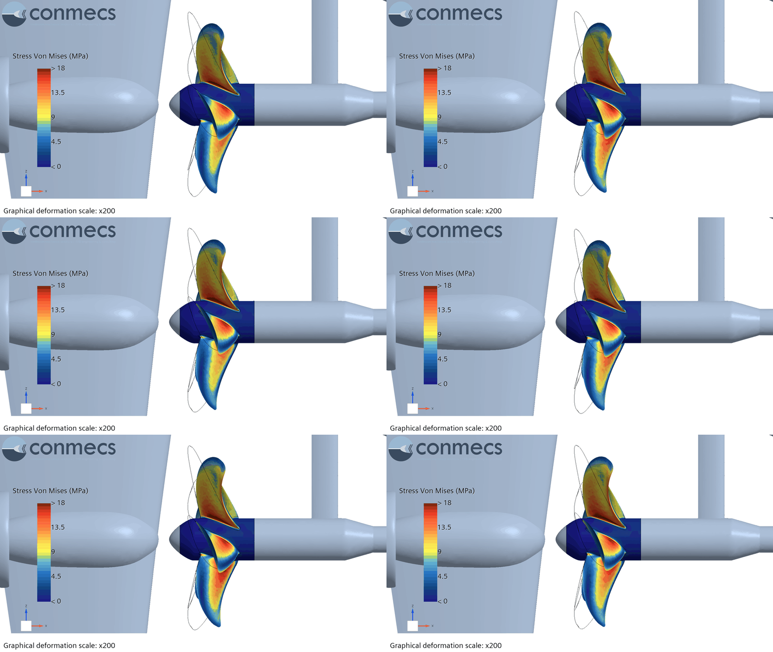
The animations show the structural response of all five blades during rotation through the vessel wake. The time histories provide a simultaneous view of the changing hydrodynamic blade loads and the corresponding deformation. For visualization, the structural deformation is amplified by a factor of 200.
From Blade Load to Structural Stress
The one-way FSI analysis also allows the local structural response to be related directly to the instantaneous hydrodynamic loading of an individual blade.
In the following animation, Blade 1 is highlighted in light blue to track its passage through the non-uniform vessel wake. The corresponding time histories show how the transient hydrodynamic blade thrust translates into elastic blade deformation and blade-root stress during one complete propeller revolution.
Tracking a Single Blade Through the Vessel Wake
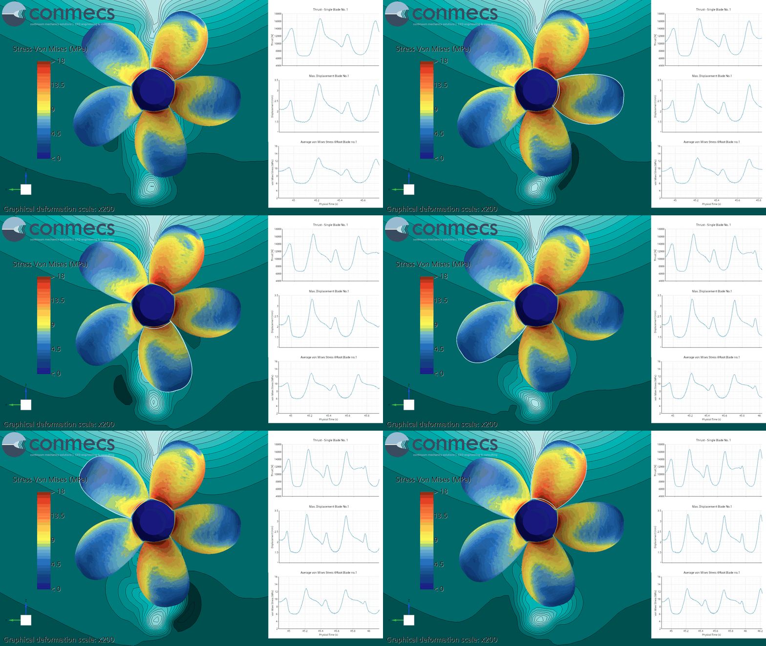
The simultaneous evaluation of flow, blade loading, deformation and stress makes it possible to identify critical angular positions and to understand the physical origin of the resulting structural response.
Engineering Application
The combination of MRF, transient Sliding Mesh CFD and one-way FSI provides a continuous analysis chain from vessel wake and propeller performance to transient blade loading and structural response.
The Sliding Mesh approach resolves the cyclic loading of individual blades as they rotate through the spatially varying wake, while the structural analysis extends the evaluation to blade deformation and stress.
This methodology can support propeller design assessment, the identification of critical blade positions and wake-induced load variations, structural evaluation of highly loaded blades, and the comparison of alternative propeller or aft-ship configurations.
The same CFD–FSI methodology can be applied to other hydrodynamically loaded appendages and devices, such as stabilizer fins and Energy Saving Devices (ESDs), to assess their transient loading and structural response under realistic operating conditions.
Case Setup
| Parameter | Configuration |
| Scale | Full scale |
| Vessel speed | 10 kn |
| Propeller diameter | 2.9 m |
| Number of blades | 5 |
| Propeller speed | 121.5 rpm |
| Flow simulation | URANS |
| Propeller modelling | MRF / Sliding Mesh |
| Structural coupling | One-way FSI |
| Structural model | Finite-volume solid |
| Propeller material | Nickel-Aluminium Bronze |