
Protective grids at bow-thruster openings interact with the external hull flow and can therefore influence vessel resistance. Aligning the grid bars with the incoming flow appears to be the hydrodynamically favourable solution, as it minimises the direct resistance of the grid itself.
The CFD analysis showed that the overall behaviour is governed by more than the grid resistance alone. The transverse grid orientation changed the flow through the bow-thruster tunnel and the surrounding pressure distribution, ultimately resulting in the lowest overall vessel resistance.
Investigated Configurations
Three configurations were investigated under identical operating conditions: an open bow-thruster tunnel without a protective grid and two grid arrangements with horizontal and vertical bar orientation.
A transient CFD approach was used to compare the overall vessel resistance as well as the local hydrodynamic behaviour around and through the bow-thruster opening.
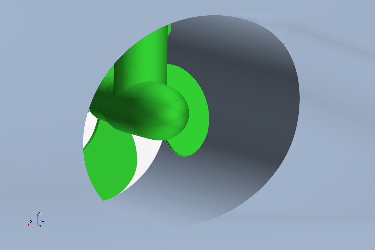
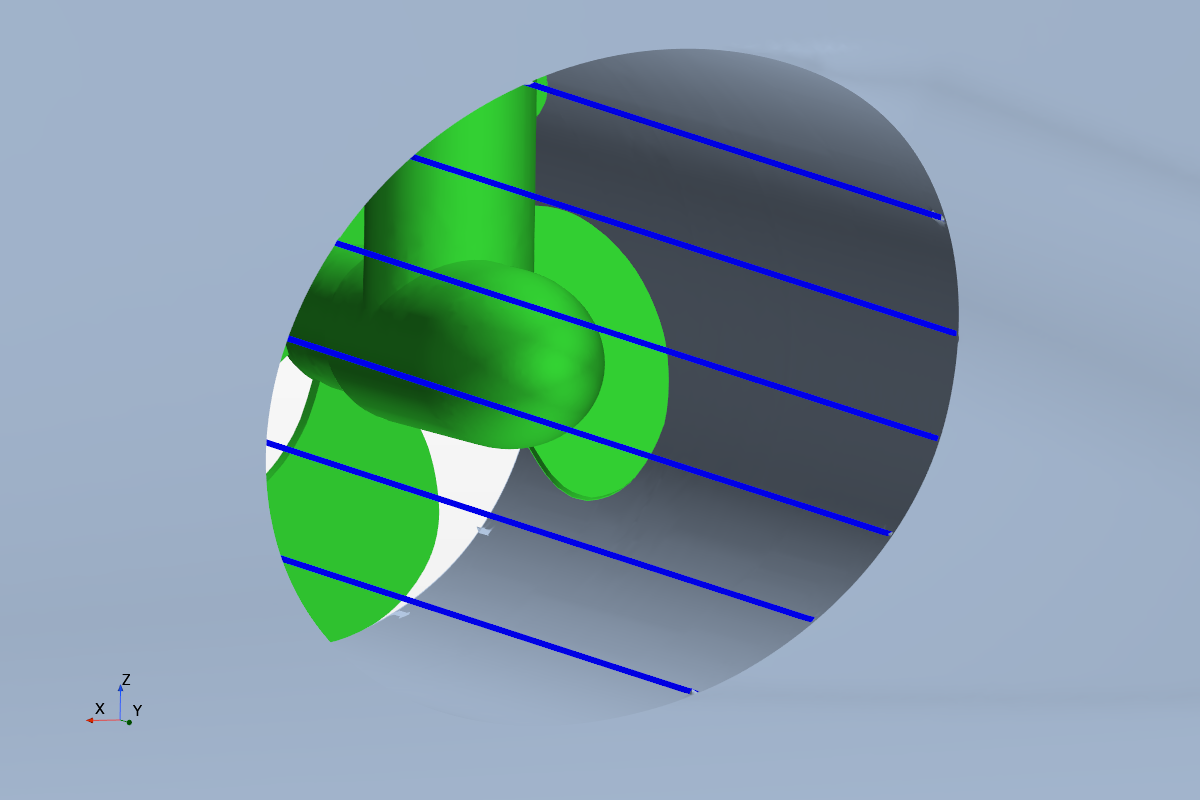
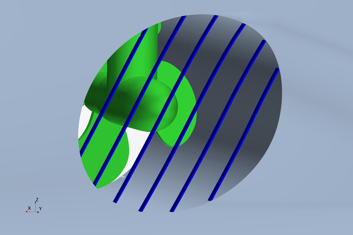
| Open Tunnel – Baseline No protective grid | Horizontal Grid Grid bars approximately aligned with the external hull flow | Vertical Grid Grid bars transverse to the external hull flow |
Comparative full-scale CFD · double-body approach · 1° oblique inflow · identical operating conditions
Measurable Reduction in Vessel Resistance
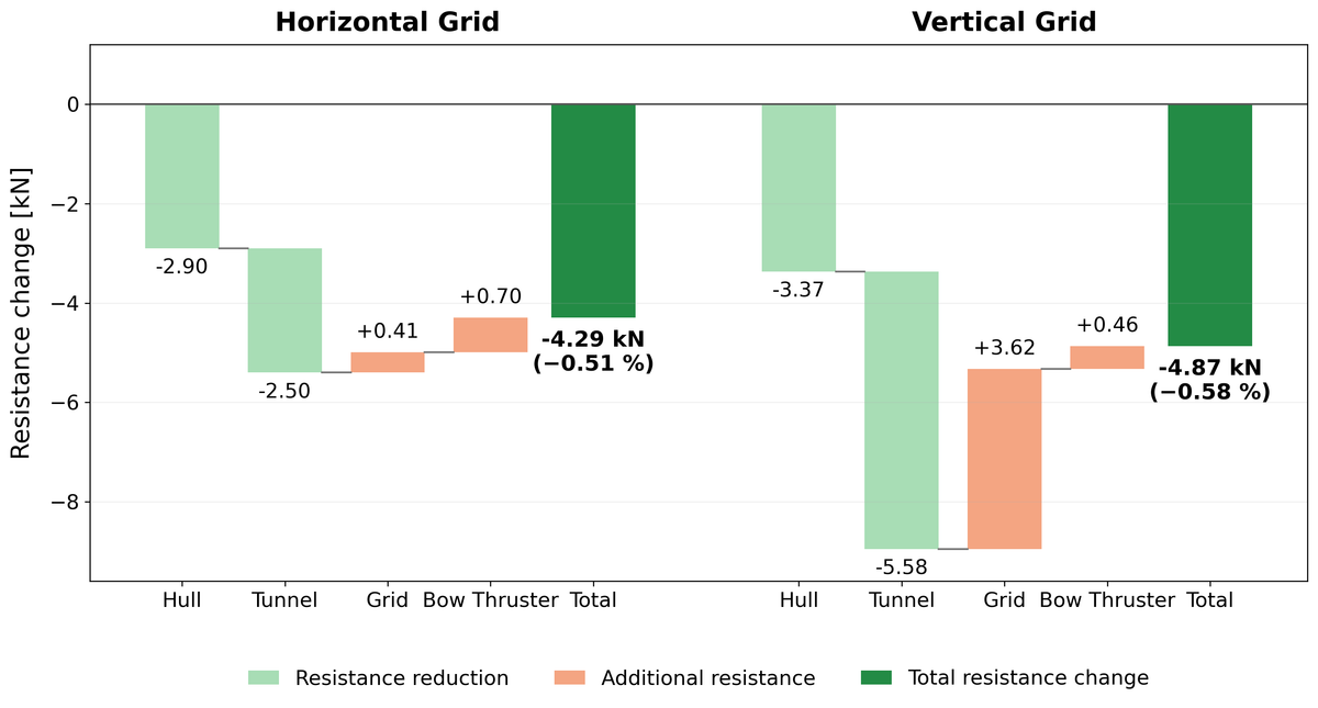
Both protective grid configurations resulted in a measurable reduction in overall vessel resistance compared with the open tunnel. The horizontal grid reduced the total resistance by approximately 0.51 %, while the lowest resistance was obtained with the vertical grid, with a reduction of approximately 0.58 %.
At first glance, this result appears counter-intuitive. The horizontal grid is approximately aligned with the external flow and produces considerably less direct grid resistance. The force decomposition, however, reveals that the interaction between hull, tunnel and grid is more important than the resistance of the grid considered in isolation.
More Than Grid Resistance
The resistance breakdown illustrates the different hydrodynamic behaviour of the two grid orientations.
With the horizontal grid, the additional resistance generated by the grid itself is very small. The vertical grid produces considerably more direct grid resistance, but at the same time reduces the resistance contribution of the bow-thruster tunnel much more effectively.
For the vertical configuration, the additional grid resistance of approximately 3.6 kN is more than compensated by a reduction of approximately 5.6 kN at the tunnel and a further favourable change in the hull resistance.
The result is a net reduction of approximately 4.9 kN, corresponding to 0.58 % of the total vessel resistance for the investigated operating condition.
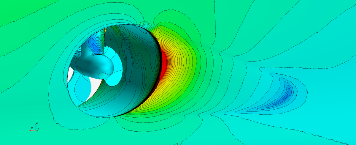
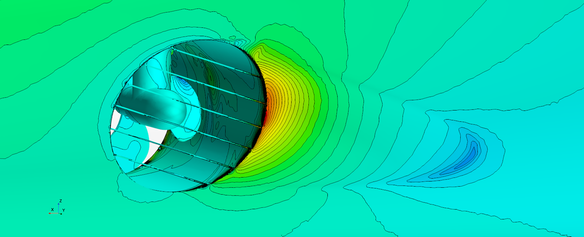
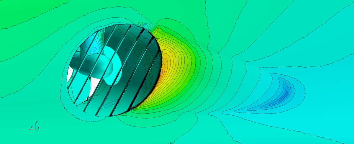
Pressure distribution around the bow-thruster opening. Identical colour scale and viewing angle are used for all configurations.
Influence on the Tunnel Flow
The CFD results show that the orientation of the grid bars also has a significant influence on the flow through the bow-thruster tunnel.
The vertical grid orientation restricts the cross-flow through the tunnel more effectively and modifies the pressure distribution around the tunnel opening. Compared with the horizontal grid, the resulting tunnel flow is considerably more stable.
This behaviour is also reflected in the transient results: the vertical grid configuration shows substantially smaller fluctuations in tunnel forces, transverse loads and mass flow.
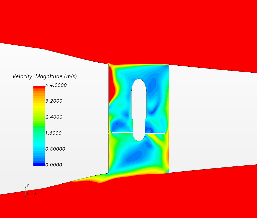
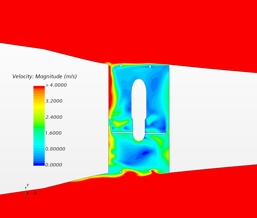
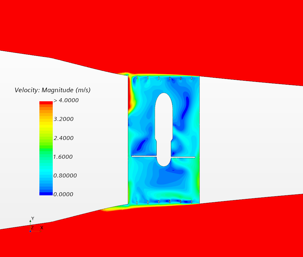
Velocity distribution through the bow-thruster tunnel at the central horizontal section. Identical velocity scale for all configurations.
Small Detail – Measurable Impact
The study demonstrates that the hydrodynamic performance of a component cannot always be assessed in isolation. Although aligning the grid bars with the external flow minimises the resistance of the grid itself, the interaction between grid, tunnel and hull ultimately favours the transverse orientation for the investigated operating condition.
Even comparatively small design changes can have a measurable impact on vessel resistance and local hydrodynamic behaviour.
CFD makes these interactions visible and provides a practical basis for evaluating design alternatives before implementation.